Create 3D By Volume
 Used to create a terrain
modeling computed by volume from another reference surface.
Used to create a terrain
modeling computed by volume from another reference surface.
You can access this tool from the following:
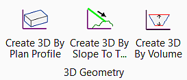
Use the Create 3D by Volume tool to create a 3D element computed by volume from a closed reference civil element. One example of tool usage is creation of a top of pond element from the bottom of pond reference element, to which a linear template may be added as an end condition to tie to a terrain model.
Prerequisite:
To use this tool, your active file must contain either Horizontal (closed) and associated vertical geometry element or 3D closed element.
| Setting | Description |
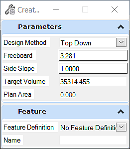
| Design Method | Bottom Up -The 3D element is designed by projecting the slope upward and outward, regardless of signage. If a negative slope is entered, the signage is ignored. Top-Down - element is designed by projecting the slope downward and inward, regardless of signage. |
| Freeboard | When the Bottom Up method is used, the Freeboard is the height from the top of the volume to the created element. For example, if the volume computes the elevation to be 205.00 and the Freeboard is 6, then the 3D element is drawn at 211.00. When the Top Down method is used, the Freeboard is the height from the bottom of the volume to the created element. For example, if the volume computes the elevation to be 205.00 and the Freeboard is 6, then the 3D element is drawn at 199.00. |
| Side Slope | Slope drawn from referenced geometry element. Field uses percentage, but alternate values may be entered (i.e., 1:50) and are automatically converted. Signage is ignored, as direction is determine by the selected Design Method. |
| Target Volume | Volume for the element (in master units, cubic feet or cubic meters) using the two 3D elements and the projected slopes to form a closed volume. If the Volume cannot be attained, a message is displaying indicating no solution. |
| Plan Area (Display only) | After creation, plan area of the newly created closed element is displayed in the tool settings (in master units, square feet or meters). |
| Feature Definition | Feature definition used as a basis for symbology of the created element. |
| Name | Name of created element, default based on Feature Definition settings. |
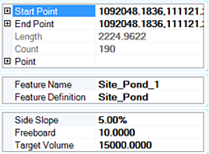
Element Handlers and Properties
Three element handlers are placed with the element and are editable:
Selecting the properties of the 3D element displays related properties:
Workflow: To Create a 3D Element by Volume
| Prompt | User Action |
| Select Element | Graphically select the closed Civil element. |
| Set Design Option | Select Bottom Up or Top Down. (Use keyboard arrows to change selection.) Data point to move to the next prompt. |
| Set Side Slope | Type in the side slope, enter, and data point to move to the next prompt. |
| Set Freeboard | Type in the freeboard (set to 0 for none), enter, and data point to move to the next prompt. |
| Target Volume | Type in the target volume, enter, and data point to move to the next prompt. |
| Data Point to Accept Design | The plan area field in the Tool Settings is now populated. Data point to complete the sequence and draw the created 3D element. If the target volume cannot be solved, an error message is displayed. |